Eight agents.One weld record.One definition of done.
Weldeon's agents are not chat assistants. Each owns a scope of the shop, holds a control authority with a hard boundary, and is measured on a number your operations director already tracks.
The roster
Deployable together or one at a time.
- 01
Cut & form
Controls plasma, laser and oxy cutting, nesting, bending and forming so plate and sections leave the front of the shop at the geometry the joint actually needs.
- 02
Fit-up & tack
Senses and controls root gap, alignment, bevel and tack placement — the single largest upstream cause of weld failure and rework.
- 03
Weld & parameter
Runs robotic arc, laser and resistance welding: heat input, travel speed, wire feed, weave and real-time seam tracking, pass by pass.
- 04
Distortion & stress
Plans weld sequence, balances heat, and predicts out-of-plane distortion and residual stress before the assembly leaves tolerance.
- 05
Defect & inspect
Reads X-ray, ultrasonic and vision data to detect and predict porosity, cracks, lack of fusion, undercut and slag — machine-read, engineer-approved.
- 06
Yield & takt
Optimises first-pass yield, rework hours and line balance across cutting, fitting, welding and finishing stations.
- 07
Robot & handling
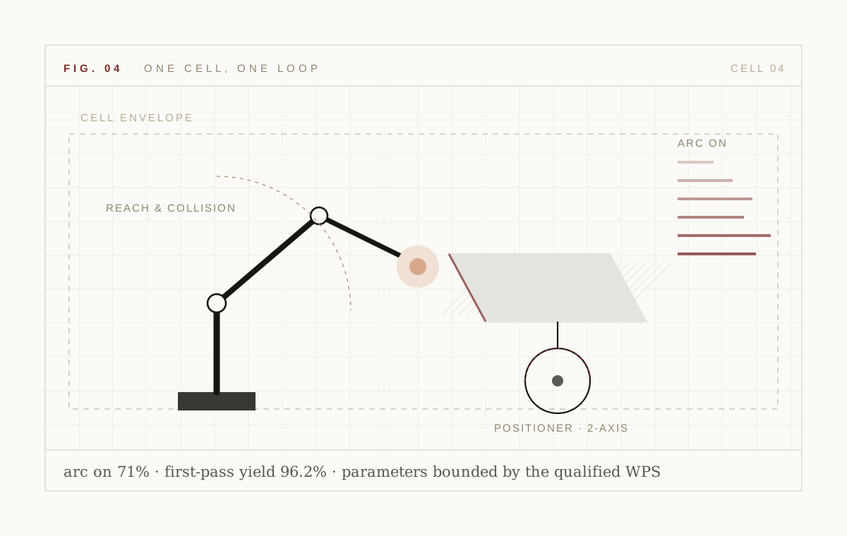
Drives welding robots, positioners, gantries and part handling — including approach, reach and collision-free motion around large weldments.
- 08
Quality & conformance
Holds right-first-time, non-conformance, weld genealogy and code traceability to AWS D1.1, ASME BPVC, ISO 3834 and EN 1090.
Upstream: geometry and fit-up
Most weld failures are decided before the arc strikes. The first two agents own the causes.
Cut and form
Controls plasma, laser and oxy cutting, nesting, bending and forming. It holds kerf compensation, bevel angle and springback so the parts arriving at the fitter match the joint the weld agent expects — and it nests for yield on the plate you actually have, not the plate in the drawing.
- Kerf, bevel and springback compensation
- Nesting for plate yield and remnant reuse
- Geometry handed forward to the twin, not re-measured
Fit-up and tack
Measures and controls root gap, alignment, bevel and tack placement. Fit-up is the largest upstream cause of lack of fusion and rework, and it is the step most often left to judgement. The agent measures the joint, decides whether it is weldable, and places tacks where the distortion model wants them.
- Gap, alignment, bevel and root-face measurement
- Go/no-go against the WPS envelope
- Tack placement chosen on the distortion model
The arc: parameters and heat
The weld agent makes the pass. The distortion agent decides the order in which passes are made.
Weld and parameter
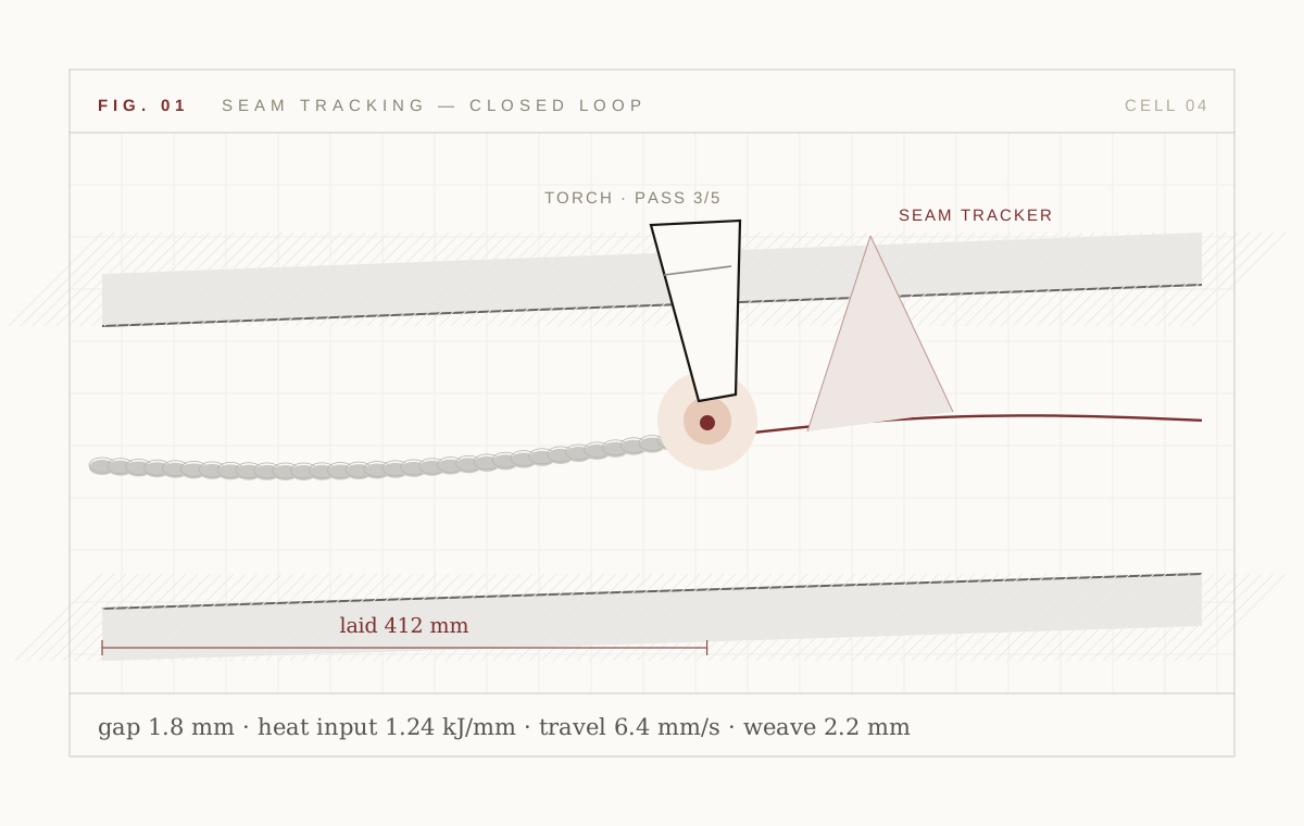
Runs robotic arc, laser and resistance welding with live seam tracking. Heat input, travel speed, wire feed, weave and torch angle are held inside the qualified envelope and adapted continuously to the joint in front of the torch.
- GMAW, GTAW, FCAW, SAW, laser and resistance
- Through-arc and laser seam tracking
- Every parameter write logged against the WPS
Distortion and stress
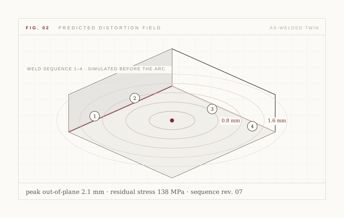
Plans sequence and heat balance, then predicts out-of-plane distortion and residual stress. On large weldments this is the difference between an assembly that fits at final and one that goes to the straightening bay.
- Sequence and balance planning
- Residual-stress hot-spot prediction
- Pre-camber and restraint recommendations
Downstream: proof and rate
One agent proves the weld is sound. The other makes sure the shop still hits rate.
Defect and inspect
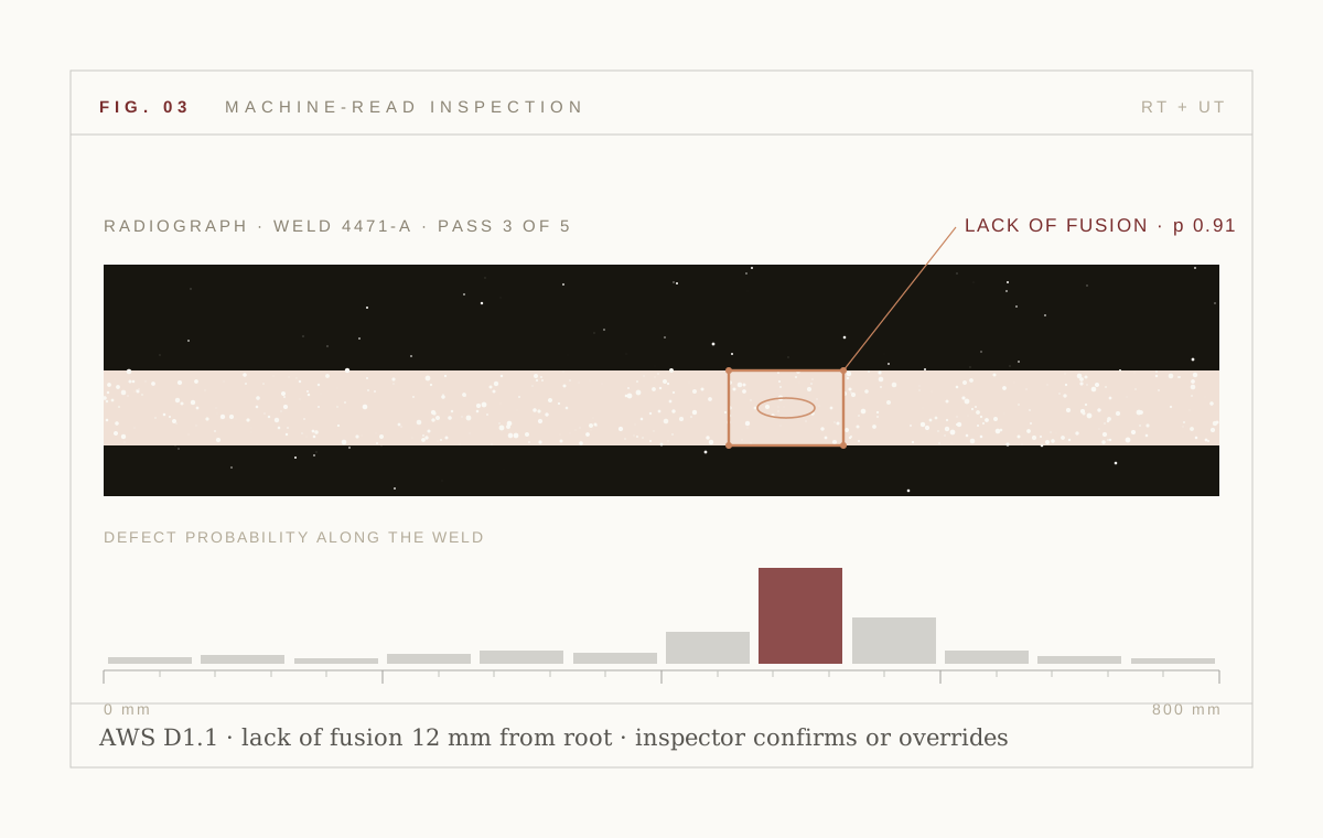
Reads digital radiography, phased-array ultrasonic and vision to detect porosity, cracks, lack of fusion, undercut and slag — and predicts them from arc signature and fit-up before the NDT bay ever sees the part. Calls carry a confidence figure and route to your qualified inspector.
- RT, PAUT and vision interpretation
- Predictive indications from arc signature
- Inspector-in-the-loop by design
Yield and takt
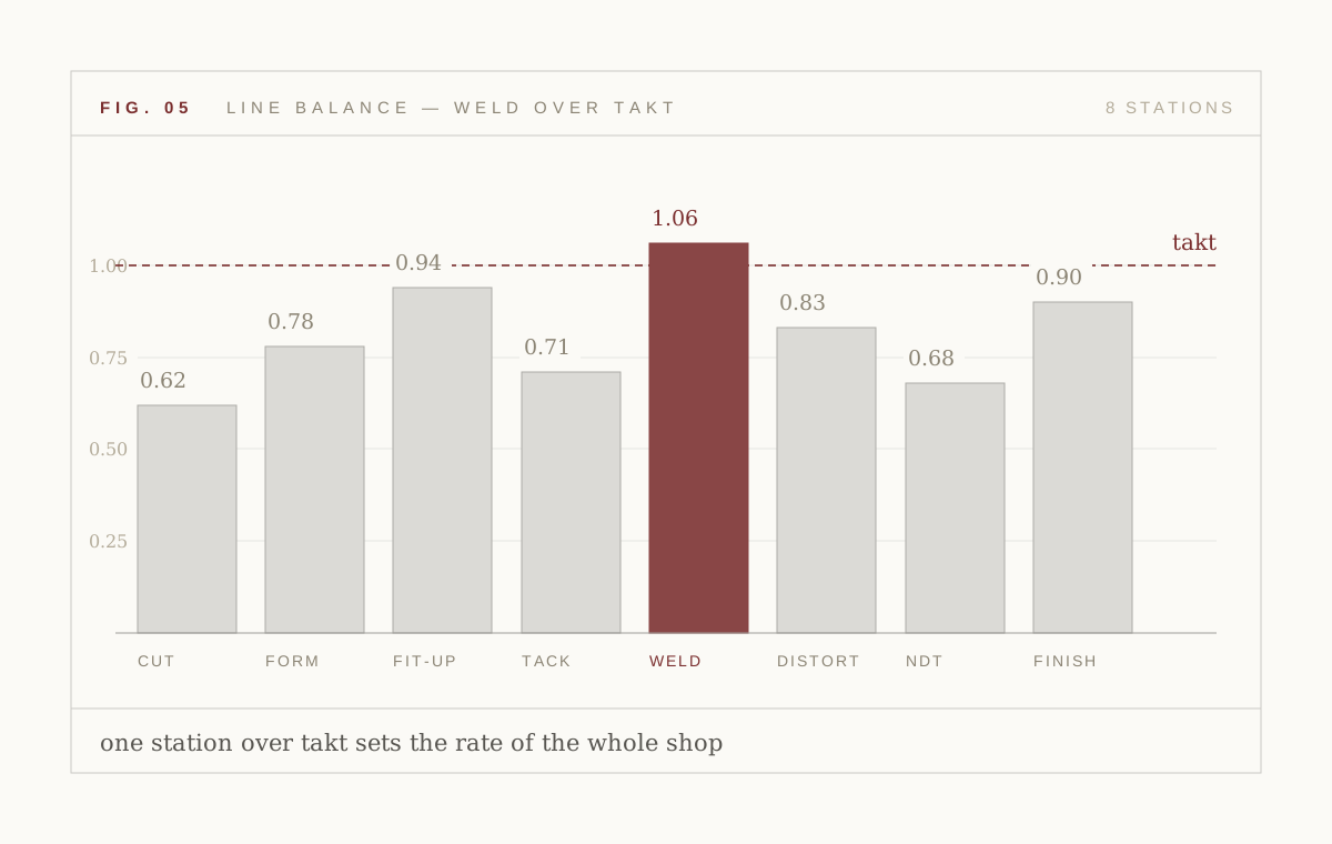
Optimises first-pass yield, rework hours and line balance across every station. It shows the operations director which station is actually costing rate, and what moving it would be worth.
- First-pass-yield and rework attribution
- Station-level takt balance
- Scenario modelling before you move a fixture
Motion and conformance
The last two agents move the metal and prove the paperwork.
Robot and handling
Drives welding robots, positioners, gantries and part handling — approach, reach, collision-free motion and re-orientation around large weldments, so the torch arrives at the joint in the position the WPS assumed.
- Motion planning around fixtures and weldments
- Positioner and gantry coordination
- Part handling, loading and re-orientation
Quality and conformance
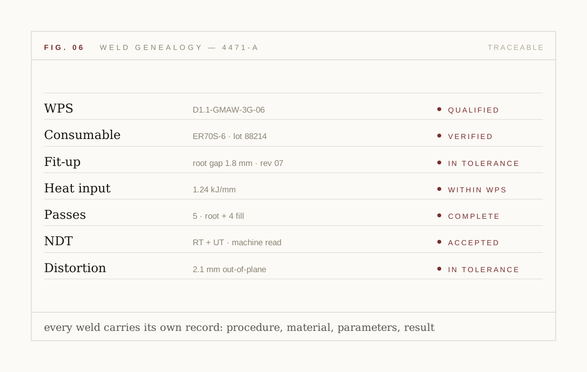
Holds right-first-time, non-conformance handling, weld genealogy and code traceability. Every weld carries its WPS, consumable lot, fit-up record, heat input, pass history, NDT result and distortion measurement.
- AWS D1.1, ASME BPVC, ISO 3834, EN 1090
- Welder and procedure qualification tracking
- Audit-ready export for client and notified-body review
How eight agents avoid arguing
Agents do not negotiate in prose. They share one part model, one weld record and one constraint set, and the conformance agent holds the veto.
- 01
One part model
Geometry, material, joints and fixtures are represented once. An agent that changes the part changes it for everyone.
- 02
One constraint set
The WPS envelope, code requirements and cell safety limits are a shared boundary, not per-agent configuration.
- 03
Explicit hand-offs
Fit-up hands a measured joint forward; the weld agent hands a pass history back. Nothing is inferred across a boundary.
- 04
Conformance has the veto
If a proposed action would break code traceability or leave the qualified envelope, it does not run. There is no override path in software.
- 05
Humans hold the escalation
Low confidence, novel joints and non-conformances escalate to a named person with the full record attached.
Each agent carries a number
FPY
first-pass yield — weld, fit-up and inspect agents
Rework
hours recovered — yield, distortion and weld agents
Escapes
defect escapes to NDT re-inspection — inspect agent
Takt
station cycle against line takt — yield and robot agents
Figures on this page describe the pilot scorecard Weldeon underwrites with design partners. They are target outcomes, not audited customer results; customer names and traction are not yet public.
“An agent that cannot be measured on a number the plant already tracks is a demo, not a deployment.”
What the agents are not allowed to do
Autonomy in a code-bound, safety-critical process needs explicit limits. These are ours.
- Leave the qualified envelope
- No agent can write a parameter outside the qualified WPS range. The boundary is enforced in the controller adapter, not in a prompt.
- Approve its own weld
- Machine-read NDT produces calls and confidences. Acceptance remains with your qualified inspector.
- Change code interpretation
- Code requirements are configuration held by your quality engineer. Agents read them; they never edit them.
- Act at low confidence
- Below the site's confidence threshold the cell stops or degrades to advisory. Guessing is not a mode.
- Hide a deviation
- Every deviation, override and stop is written to the genealogy record before the next pass begins.
Agent questions
-
No — and most shops should not. Land on the one agent attached to your most expensive pain line, prove it on a cell, then expand. The Cell plan exists precisely for this.
-
The reasoning layer uses learned models across several families — vision and signal models for perception, physics-informed models for the twin, and policy models for control. Language models are used where language is the problem: procedures, reports and genealogy summaries.
-
The platform recognises that the joint is out of distribution, drops to advisory, and asks for a supervised run. Novel geometry is added to the twin before it is welded autonomously.
Bring autonomy to thearc, the fit-up andthe inspection bay.
Book a pilot on one cell or line. We agree the scorecard before we start — first-pass yield, rework hours, defect escapes, takt — and we report against it in the open.